
Hey there, Telecaster enthusiasts! If you’re looking to explore the vast tonal possibilities of your Tele, understanding its wiring is key. At guitarplayers.net, we’re diving deep into the world of wiring diagrams for Telecaster guitars. This guide will be your one-stop resource for understanding various Tele wiring configurations, their nuances, and how they can shape your sound. Let’s get wired!
Before we jump in, remember that in these diagrams, ground connections are often implied for clarity. Ensure all electronic components are properly grounded when you’re working on your guitar.
Exploring Telecaster Wiring Options
The Telecaster, known for its simplicity and versatility, offers a surprising number of wiring variations. From classic configurations to modern modifications, each wiring scheme unlocks a unique set of tones. Let’s explore some of the most popular and effective wiring diagrams for Telecaster guitars.
Modern Telecaster Wiring: The Standard
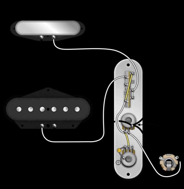
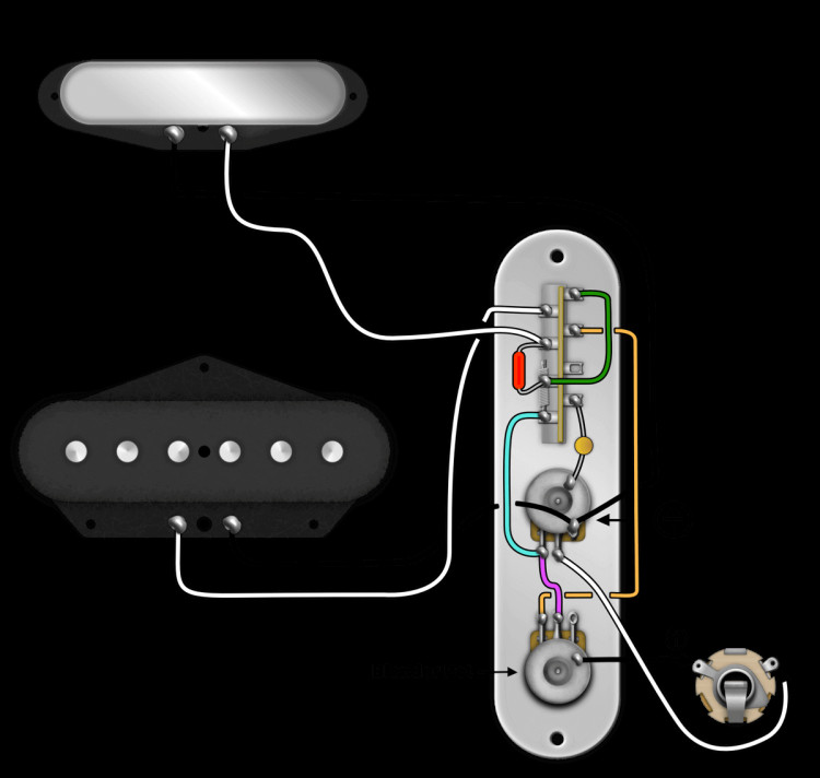
The modern Telecaster wiring is the most common setup you’ll find on contemporary Teles. It’s a versatile and reliable configuration, making it a standard across genres and playing styles. If you own a Telecaster made after 1967, chances are it’s wired this way. This setup features a 3-way blade switch, a master volume, and a master tone control. Here’s a look at the diagram:
[Diagram of Modern Telecaster Wiring]
But did you know there’s a slightly different way to achieve the same modern Telecaster wiring result? This alternate version functions identically to the standard one, but some find it easier to wire. It eliminates the need for that small, “S”-shaped jumper on the switch, making it a bit more accessible for some DIYers. Check out Version 2:
 Standard Telecaster Wiring, Alternate Version
Flipped Control Plate Wiring for Telecasters
For players who prioritize quick access to the volume control, the flipped control plate modification is a game-changer. In a standard Telecaster setup, the 3-way switch is closest to your strumming hand. If you like to make volume adjustments on the fly, reaching past the switch can be a bit cumbersome.
The flipped Telecaster control plate wiring addresses this by rearranging the controls. It places the volume pot first, followed by the tone control, and finally the blade switch. This configuration puts the volume knob right under your pinky finger, perfect for volume swells and on-the-fly adjustments. Want a deeper dive? Read our dedicated article on the flipped control plate Telecaster. Otherwise, here’s the wiring diagram for a flipped control plate Telecaster:
[Diagram of Flipped Control Plate Wiring]
Considering this modification? Keep in mind that you might need to extend your pickup leads, as they’ll need to reach further to connect to the switch in this configuration.
Unleashing More Tones with 4-Way Switching
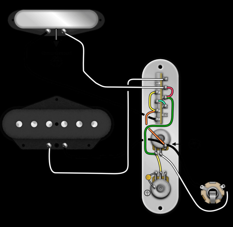
Three pickup positions are great, but what if you could unlock even more tonal variety from your Telecaster? Enter 4-way switching. Popularized by models like the Fender Baja 60s Telecaster, this wiring mod expands your sonic palette significantly.
Here’s how the pickup positions are arranged in a 4-way switching Telecaster wiring diagram:
- Position 1: Bridge Pickup
- Position 2: Bridge and Neck Pickups (in Parallel)
- Position 3: Neck Pickup
- Position 4: Bridge and Neck Pickups (in Series)
That fourth position, the series connection, is where the magic happens. It creates a thicker, hotter, and more powerful tone by essentially turning your two single-coil pickups into a humbucker. To learn more about the sonic possibilities, explore our article on 4-way switching for Telecasters.
 4 Way Switching Diagram
Nashville Telecaster Wiring: Adding a Middle Pickup
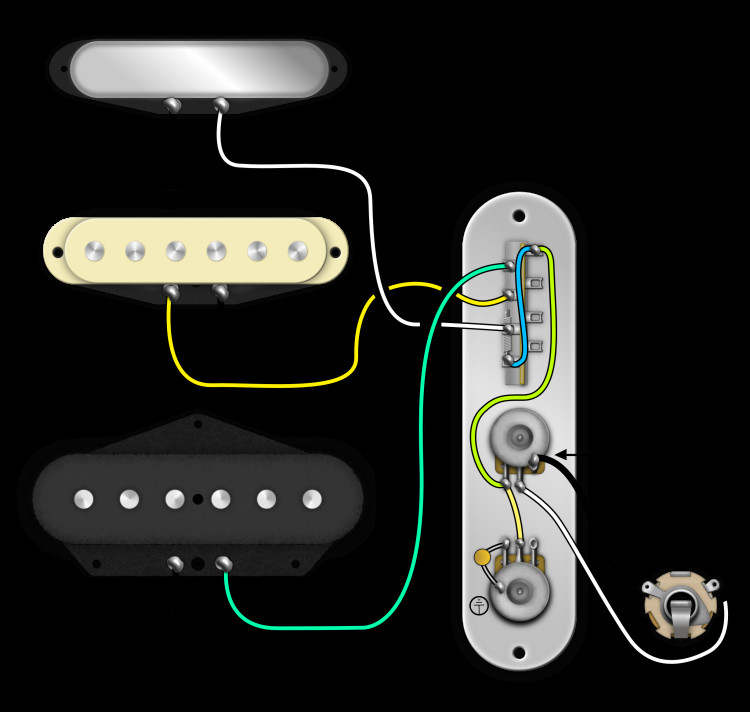
The Nashville Telecaster takes the Tele formula and adds a Stratocaster-style middle pickup. This configuration, often called “B-Bender Tele” due to its association with B-Bender equipped guitars played in Nashville, delivers a broader range of tones, closely resembling Stratocaster wiring in its switching logic.
In a traditional Nashville Telecaster wiring diagram, the 5-way switch positions are as follows:
- Position 1: Bridge Pickup
- Position 2: Bridge and Middle Pickups (in Parallel)
- Position 3: Middle Pickup
- Position 4: Middle and Neck Pickups (in Parallel)
- Position 5: Neck Pickup
 A diagram of Nashville Telecaster Wiring
Converting a standard Telecaster to a Nashville configuration can present some polarity challenges. Our article on the Nashville Tele problem offers valuable insights if you’re considering this modification.
Telecaster Custom Wiring: Les Paul Inspired Tones
The Telecaster Custom wiring blends the best of both worlds: the Telecaster’s ergonomics and the tonal flexibility of Les Paul-style wiring. This setup provides a versatile sonic palette while optimizing the electronics for your chosen pickups.
The Telecaster Custom wiring diagram typically features a 3-way switch with these positions:
- Position 1: Bridge Pickup
- Position 2: Bridge and Neck Pickups (in Parallel)
- Position 3: Neck Pickup
A key advantage of the Telecaster Custom wiring is the ability to use different value potentiometers. You can, for instance, use a 250K pot for the bridge pickup and a 500K pot for a Wide Range Humbucker neck pickup, optimizing each pickup’s tone.
Humbucker and Single Coil Tele Wiring: Balancing Act
Mixing humbuckers and single-coils in a Telecaster can be tricky due to their different tonal characteristics. Humbuckers generally sound best with 500K pots, while single-coils often shine with 250K pots to tame their brightness. This difference becomes more pronounced in guitars like Telecasters with a single volume control.
Fortunately, there’s a clever workaround using a resistor to “trick” the guitar’s pot value! The strategy is to use the recommended pot value for the darker pickup as your master volume pot. So, if you have a humbucker in the neck position, use a 500K volume pot. Then, add a 500K resistor from the bridge pickup to ground. This effectively makes the bridge pickup “see” a 250K pot. Here’s the wiring diagram for a Humbucker and Single Coil Telecaster:
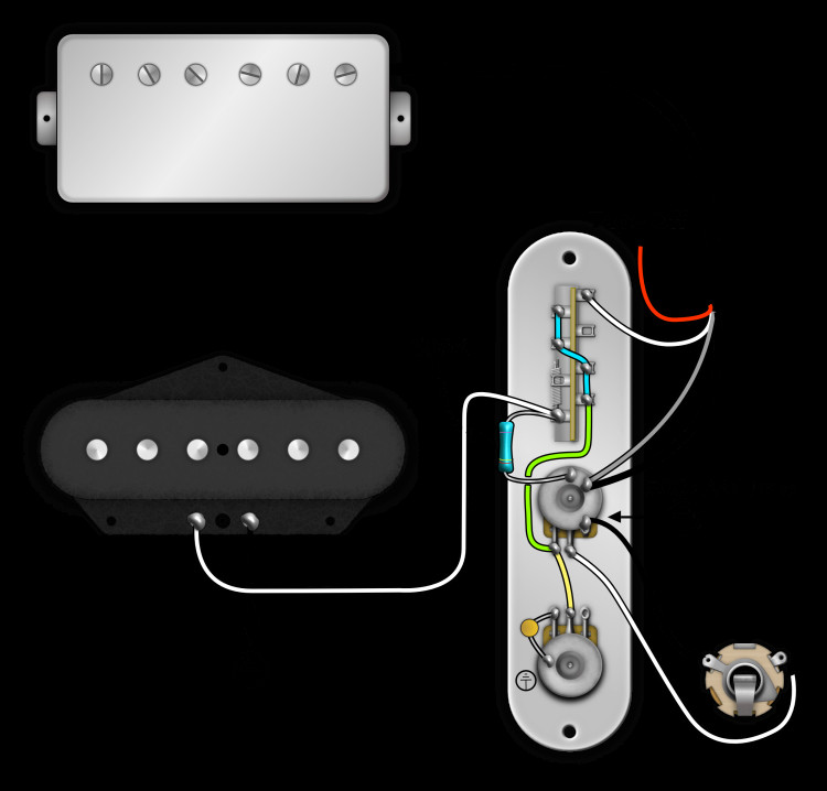 A diagram of a Humbucker and Single Coil in a Telecaster
As illustrated in the diagram, the 500K resistor is soldered to the bridge pickup connection on the switch and then grounded. For a reverse setup (single-coil neck, humbucker bridge), you’d solder the resistor to the neck pickup’s switch position. Want to learn more about pot values? Check out our guide on choosing between 250K and 500K pots and our article on mixing single coils and humbuckers.
Esquire Wiring (Eldred Modification): Hot-Rodded Simplicity
The Esquire, Telecaster’s minimalist sibling, is a cool and surprisingly versatile guitar. However, the original 1950s Esquire wiring had a position (position 3) that was considered overly dark by some players. The Eldred modification addresses this by replacing the fixed treble roll-off circuit with a low-value capacitor. The classic Eldred mod uses a 0.0047uf capacitor, but you can experiment with different values to fine-tune the tone.
Here’s how the positions work in an Esquire wiring diagram with the Eldred mod:
- Position 1: Tone control bypassed; bridge pickup direct to volume pot (brightest tone).
- Position 2: Bridge pickup through volume and tone pots (standard tone control).
- Position 3: Tone pot bypassed; bridge pickup through a small capacitor (cocked-wah tone).
Broadcaster Wiring (With Blend): Early Tele Tones
Stepping back in time, Broadcaster wiring, named after the Telecaster’s original name, introduces a neck pickup and a blend pot for unique tonal shaping. This wiring offers a distinct set of sounds reminiscent of early Telecasters.
The Broadcaster wiring diagram with a blend pot provides these positions:
- Position 1: Bridge pickup with blend pot (blend in neck pickup).
- Position 2: Neck pickup only.
- Position 3: Neck pickup only with capacitor (dark, bassy tone).
The blend pot smoothly blends in the neck pickup in position 1, offering a wide range of tonal variations. Resistor and capacitor values can vary; 15k for the resistor and 0.05mfd for the capacitor are common starting points. Experimenting with capacitor values is encouraged to tailor the dark tone in position 3 to your liking. A lower capacitance value will result in a less dark and more usable tone in modern contexts.
50s Telecaster Wiring: Vintage Roots
Finally, we arrive at the 50s Telecaster wiring, the original pre-CBS wiring scheme. While not as widely used today as more modern configurations, understanding this vintage wiring is essential for a complete picture of Telecaster wiring history.
The 50s Telecaster wiring diagram provides these positions:
- Position 1: Bridge pickup with tone control.
- Position 2: Neck pickup with tone control.
- Position 3: Neck pickup only with capacitor (dark, bassy tone).
Conclusion: Your Tele Wiring Journey
That’s a comprehensive tour through the world of wiring diagrams for Telecaster guitars! From modern standards to vintage re-creations and innovative modifications, the Telecaster offers a remarkable range of wiring possibilities to shape your sound.
Want to simplify your wiring project? We offer pre-wired Telecaster control plates to make upgrades a breeze! And for even more wiring diagrams, be sure to visit our wiring diagrams page. Happy wiring and happy playing!